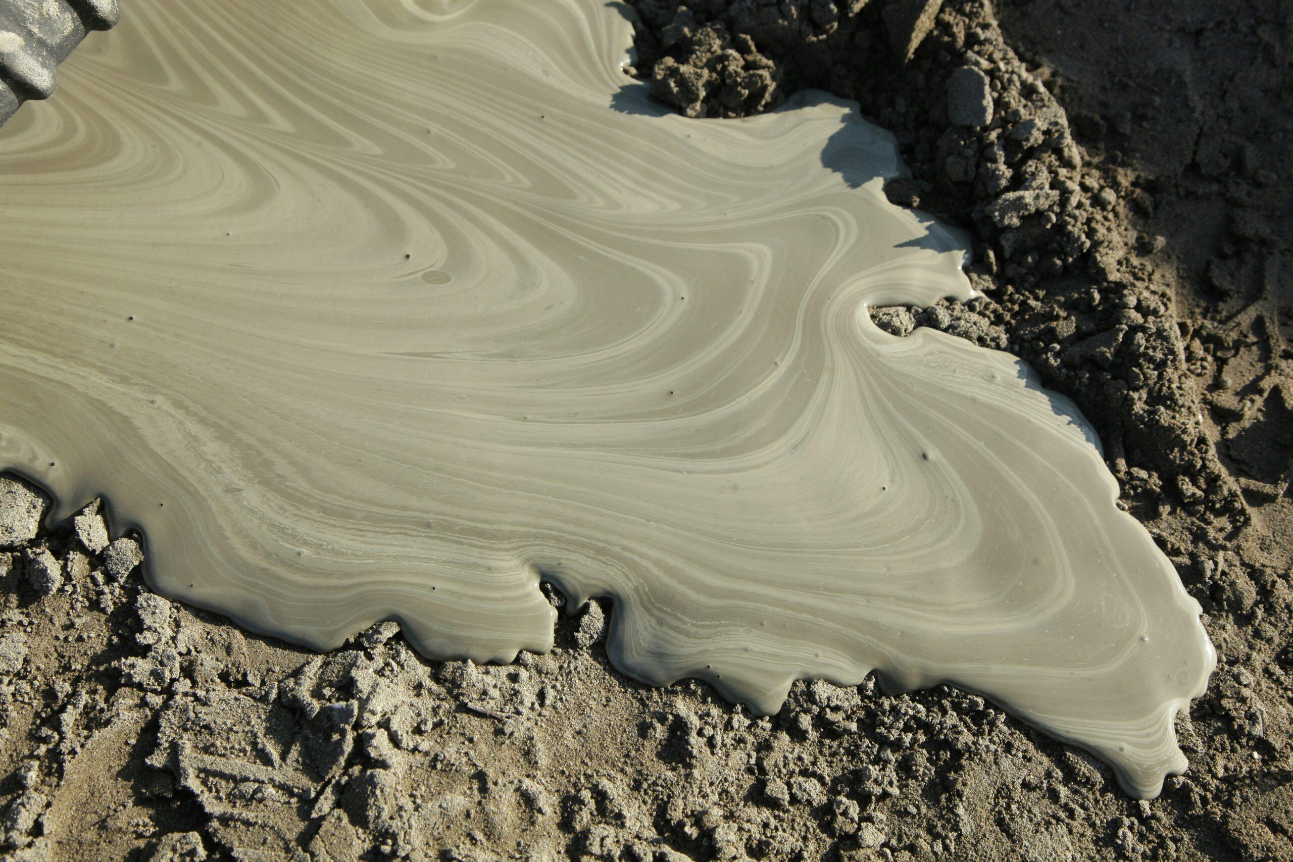
In Horizontal Directional Drilling (HDD), maintaining a consistent drilling fluid flow is essential for efficient operations. Drilling fluid can contain sand, gravel and other solids that may affect pumps and downstream equipment.
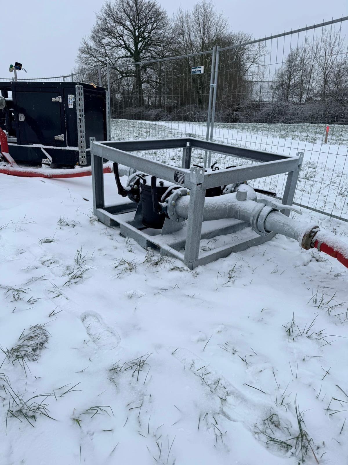
A bentonite filter skid helps protect this equipment by capturing larger particles before they enter the system. However, as solids accumulate inside the filter, flow resistance can increase.
Monitoring the pressure before and after the filter helps operators identify restrictions and determine when the filter needs attention.
Why measure pressure before and after the filter?
Measuring pressure on both sides of a drilling fluid filter provides valuable information about the condition of the filter and the flow through the system.
Each pressure gauge has a different purpose:
Inlet pressure gauge – Before the filter
The inlet pressure gauge measures the pressure of the drilling fluid entering the filter skid.
This reading helps operators monitor the pressure supplied to the filter. If the inlet pressure increases while the flow rate remains relatively constant, it may indicate increasing resistance in the system, including a possible restriction in the filter.
However, inlet pressure alone cannot confirm whether the filter is becoming blocked.
Outlet pressure gauge – After the filter
The outlet pressure gauge measures the pressure of the drilling fluid leaving the filter and continuing towards the pumps or other downstream equipment.
This reading helps operators monitor the pressure available after filtration.
A decrease in outlet pressure may indicate a change in system conditions, but does not automatically mean the filter is blocked.
Differential pressure – Comparing both readings
The most useful information comes from comparing the two pressure gauges.
The difference between inlet and outlet pressure is called the differential pressure (ΔP).
For example:
| Measurement | Clean filter | Restricted filter |
|---|---|---|
| Inlet pressure | 3.0 bar | 3.5 bar |
| Outlet pressure | 2.7 bar | 2.5 bar |
| Pressure difference | 0.3 bar | 1.0 bar |
Illustrative values under comparable flow conditions.
In this example, the pressure difference increases from 0.3 to 1.0 bar. This indicates that the resistance across the filter has increased. When flow rate and fluid properties remain comparable, an increasing differential pressure can indicate that solids are accumulating inside the filter element. By monitoring both gauges, operators can identify potential restrictions without opening the filter housing during operation.
Choosing the right filter size for HDD applications
The main purpose of a drilling fluid filter skid is to protect pumps and other downstream equipment from larger solid particles that could cause blockages, excessive wear or operational problems. The appropriate filter size depends on the drilling fluid, expected solids and the requirements of the equipment being protected.
Our SlurrySafe 6″ bentonite filter skid is available with three interchangeable filter elements:
- 3 mm: For retaining smaller particles where finer filtration is required.
- 5 mm: An intermediate filtration option.
- 8 mm: For retaining larger particles where coarser filtration is sufficient.
These filter elements are designed to remove larger solids rather than fine particles suspended in the drilling fluid.
What can pressure readings tell you during operation?
By regularly comparing inlet and outlet pressure, operators can recognize changes in filter performance. An increasing pressure difference under similar operating conditions can indicate that the filter is gradually becoming restricted. A relatively stable pressure difference generally suggests that the resistance across the filter has not changed significantly.
If both pressure readings change together while the pressure difference remains similar, the cause may be related to changes in pump output, flow rate or other system conditions rather than the filter itself.
There is no universal pressure difference at which every filter needs cleaning. Flow rate, drilling fluid viscosity and filter element size all influence the readings.
The most practical approach is to establish normal operating values with a clean filter and monitor how these change during use.
SlurrySafe 6″: Protecting pumps and downstream equipment
The SlurrySafe 6″ filter skid is designed to protect pumps and other HDD equipment by filtering larger solid particles from drilling fluid. Equipped with pressure gauges on both the inlet and outlet, the filter skid allows operators to monitor the pressure difference across the filter during operation. Its interchangeable 3, 5 and 8 mm filter elements make it possible to adapt filtration to different drilling conditions and equipment requirements. By combining mechanical filtration with straightforward pressure monitoring, the SlurrySafe 6″ provides a practical solution for protecting downstream equipment and identifying when the filter may require cleaning or inspection.
The principle is simple: the inlet gauge shows the pressure entering the filter, the outlet gauge shows the pressure leaving it, and the difference between the two helps operators monitor filter resistance.